The Wio Terminal is a SAMD51-based microcontroller with a builtin display, various sensor buttons and a Raspberry Pi compatible GPIO. This guide gives examples on using the built in features with Adafruits CircuitPython
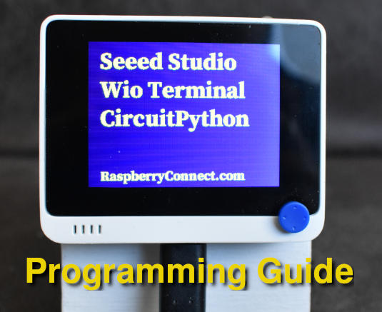
The Wio Terminal has several built in features that can be accessed using CircuitPython.
- LCD Display 320 x 240
- Duel Band WiFi
- Bluetooth 5
- Three programmable buttons
- Five way programmable switch
- Two Mutifunction Grove connections
- Buzzer
- Microphone
- Light Sensor
- IR Transmitter 940nm
- Micro SD slot
CircuitPython is available for the Wio Terminal from version 7 which can be used to access all the features of the Wio Terminal except for WiFi and Bluetooth. If you need to use WiFi or Bluetooth then currently you will need to use Ardunio IDE instead.
CircuitPython on the Wio Terminal
This guide will go through how to access the the Wio Terminal using CircuitPython based on the examples on the Adafruit's website, by making the required changes to get your projects started. learn.adafruit.com
To get started the CircuitPython firmware needs to be installed before you can start programming. This is available at circuitpython.org/board/seeeduino_wio_terminal
Next download the libraries to match the firmware, to a computer. circuitpython.org/libraries
To load the firmware connect the Wio Terminal to a computers usb port. Then slide the power switch down twice, quickly. The computer should now show a new USB device called Arduino. Drag the circuitpython .UF2 file to the Ardunio drive. The Wio Terminal will reset after a few seconds and the CIRCUITPY drive will appear.
Use the programs MU or Thonny to program in CircuitPython and run the code.
Copy the required libraries from the ZIP file that was save to the computer over to the CIRCUITPY/lib folder. Any programme called code.py or main.py will run automatically when the device is switched on.
Now that the initial setup is done we can start programming. The first thing to get setup is the display.
GPIO Pin names
The GPIO pin names that are used with the board. command can be listed by running the commands:
import board
print(dir(board))
this gives the list
'A0', 'A1', 'A2', 'A3', 'A4', 'A5', 'A6', 'A7', 'A8', 'BUTTON_1', 'BUTTON_2', 'BUTTON_3', 'BUZZER', 'CS', 'D0', 'D1', 'D10', 'D13', 'D2', 'D3', 'D4', 'D5', 'D6', 'D7', 'D8', 'D9', 'DAC0', 'DAC1', 'DISPLAY', 'GYROSCOPE_INT', 'GYROSCOPE_SCL', 'GYROSCOPE_SDA', 'I2C', 'I2S_BCLK', 'I2S_LRCLK', 'I2S_SDIN', 'I2S_SDOUT', 'IR', 'LED', 'LIGHT', 'MIC', 'MISO', 'MOSI', 'RTL_CLK', 'RTL_CS', 'RTL_DIR', 'RTL_MISO', 'RTL_MOSI', 'RTL_PWR', 'RTL_READY', 'RTL_RXD', 'RTL_TXD', 'RX', 'SCK', 'SCL', 'SDA', 'SD_CS', 'SD_DET', 'SD_MISO', 'SD_MOSI', 'SD_SCK', 'SPI', 'SWITCH_DOWN', 'SWITCH_LEFT', 'SWITCH_PRESS', 'SWITCH_RIGHT', 'SWITCH_UP', 'TFT_BACKLIGHT', 'TFT_CS', 'TFT_DC', 'TFT_MISO', 'TFT_MOSI', 'TFT_RESET', 'TFT_SCK', 'TX', 'UART', 'board_id'
These can be used to access the various features of the Wio Terminal.
Programming the Display
As the display is built in, there is no I2C or SPI setup required, the display can simply be initialised with
lcd = board.DISPLAY
This is a simple example to display text on the screen. First all the required libraries need to be added to CIRCUITPY/lib
For this you only need to add 'adafruit_display_text' to the lib folder as all the other libraries are built into the firmware.
#Wio Terminal Display
import board
import time
import displayio
import terminalio
from adafruit_display_text import label

lcd = board.DISPLAY

LCD_w = 320
LCD_h = 240

font = terminalio.FONT

def display(txt):
    screen = displayio.Group()
    color_bitmap = displayio.Bitmap(LCD_w, LCD_h, 1) #Width, Height, Colours
    color_palette = displayio.Palette(1)
    color_palette[0] = 0x333366
    bg = displayio.TileGrid(color_bitmap, pixel_shader=color_palette, x=0, y=0)
    screen.append(bg)
    screen.append(label.Label(font, text=txt, color=0xFFFF00, x=40, y=50))
    lcd.show(screen)


words = ("Seeed Studio","Wio Terminal","CircuitPython","RaspberryConnect.com")
while 1:
    for i in range(len(words)):
        display(words[i])
        time.sleep(1)
This shows the entries in the 'words' list on screen.
You will noticed that the font is very small. This is because it is the built in font. If you want a bigger font then a bitmap font is required. These can be created with FontForge for which there is a how to guide on the adafruits website.
To use bitmap font you will need to add the 'adafruit_bitmap_font' library and import it. I will be using the SerifPro-Bold-22.pcf font that was previously prepared and saved in the CIRCUITPY folder, for the rest of this guide. To use this replace the terminalo.FONT as follows
from adafruit_bitmap_font import bitmap_font as bitf
then replace
font = terminalio.FONT
with
font = bitf.load_font("/SerifPro-Bold-22.pcf")
Now the Text will be larger. The SerifPro-Bold-22.pcf font is available at the base of this article.
Display Backlight Control
When a program is not required it is always good to put the microcontroller to sleep to save energy especially if your project uses a battery. Unfortunately the alarm features don't seem to be available for the Wio Terminal in version 7 so it can't be set to a deep sleep and awake on an event. You can use time.sleep() but the display will still be active. So the next option is to turn off the displays backlight. This can be done by changing the brightness level. The display can only be set as 100% or 0% brightness but it is simple.
The display was initialised with;
lcd = board.DISPLAY
To turn the backlight Off use
lcd.brightness = 0
and for On use
lcd.brightness = 1
Buttons and Switches
Now the display is working the next task is to program the three user buttons and the five way switch.
To access any buttons the built-in digitalio library is required.
The buttons and switch directions need to be initialised then the readings can be taken to show when they are pressed. Import the libraries
import board
from digitalio import DigitalInOut, Direction, Pull
To create button1, initalise it and set it as an input with these commands
but1 = DigitalInOut(board.BUTTON_1)
but1.direction = Direction.INPUT
but1.pull = Pull.UP
To see if button 1 has been pressed check the result of
but1.value
The remaining buttons and 5 way switch can be accessed the same way using the following entries with the board. command.
'BUTTON_1', 'BUTTON_2', 'BUTTON_3', 'SWITCH_DOWN', 'SWITCH_LEFT', 'SWITCH_PRESS', 'SWITCH_RIGHT', 'SWITCH_UP'
Press is True or False?
pull can be set to Pull.UP or Pull.DOWN. This effects if a button press has a value of True or False.
There is a bit of an inconsistency between the buttons and 5 way switch. The 3 Buttons are False when pressed regardless of using pull.UP or pull.DOWN.
The 5 Way Switch is False when pressed with pull.UP and True when pressed with pull.DOWN..
So that all buttons and switch positions can be controlled with one piece of code, the example below sets Pull.UP so all presses are False.
This is an example program to display the action of the buttons and switch. time.monotonic has been used so other actions can be done while waiting for a button to be pressed rather than pausing the program with time.sleep
#Seeed Studio Wio Terminal

import board
import busio
import adafruit_ds3231 # RTC
import time
import displayio
from digitalio import DigitalInOut, Direction, Pull

from adafruit_display_text import label
from adafruit_bitmap_font import bitmap_font as bitf
from adafruit_display_shapes.rect import Rect

i2c = busio.I2C(board.SCL, board.SDA)
rtc = adafruit_ds3231.DS3231(i2c)
lcd = board.DISPLAY

LCD_w = 320
LCD_h = 240
tme_m = 0

font = bitf.load_font("/SerifPro-Bold-22.pcf")

def display(txt):
    screen = displayio.Group()
    color_bitmap = displayio.Bitmap(LCD_w, LCD_h, 1)
    color_palette = displayio.Palette(1)
    color_palette[0] = 0x333366
    bg = displayio.TileGrid(color_bitmap, pixel_shader=color_palette, x=0, y=0)
    screen.append(bg)
    screen.append(label.Label(font, text=txt, color=0xFFFF00, x=80, y=50))
    lcd.show(screen)

def tm():
    global tme_m
    tme_m = time.monotonic()

def chktme():
    return time.monotonic()

controls = [board.BUTTON_1,board.BUTTON_2,board.BUTTON_3,board.SWITCH_UP,board.SWITCH_DOWN,board.SWITCH_LEFT,board.SWITCH_RIGHT,board.SWITCH_PRESS]
button_ref = ['but_1','but_2','but_3','up','down','left','right','press'] #objects to assign buttons to
button_name = ['Button1','Button2','Button3','Up','Down','Left','Right','Press'] #Display Names
for i in range(len(controls)):
    button_ref[i] = DigitalInOut(controls[i])
    button_ref[i].direction = Direction.INPUT
    button_ref[i].pull = Pull.UP

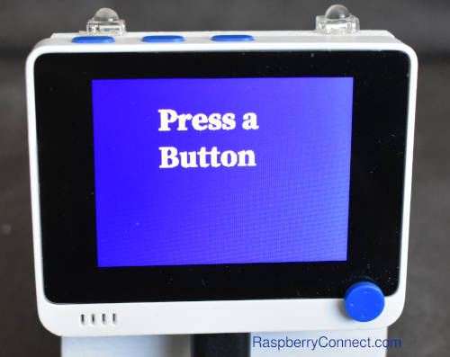
display("Press a\nButton")
while 1:
    for x in range(len(button_ref)):
        if not button_ref[x].value: #check if any button object is False so being pressed
            display(button_name[x]) #Display the name of the button that is active
            tm() #store monotonic time for delay
    if tme_m+3 < chktme(): #check delay has been more than 3 seconds
        display("Press a\nButton")
Light Sensor
The Wio Terminal has an analogue light sensor in the window at the back of the device. 0 is dark 65536 is as bright as it can detect.
The light sensor works in a similar way as a button where the value is read but as it is analogue the results will be in a scale of 0 to 65536 rather than 0 & 1.
First import the built in analogueio library, then initialise the light sensor object and finally take the readings. The Light sensor is on pin board.LIGHT.
import board
import time
from analogio import AnalogIn

lightlevel = AnalogIn(board.LIGHT)

while 1:
    print(lightlevel.value)
    time.sleep(0.2)
This code will display the results on the Wio Terminal
#Wio Terminal
import time
import board
import displayio
from adafruit_bitmap_font import bitmap_font as bitf
from adafruit_display_text import label
from analogio import AnalogIn


lcd = board.DISPLAY
lightlevel = AnalogIn(board.LIGHT) # Light Sensor pin on Wio Terminal

LCD_w = 320
LCD_h = 240


font = bitf.load_font("/SerifPro-Bold-22.pcf")

def display(txt):
    screen = displayio.Group()
    color_bitmap = displayio.Bitmap(LCD_w, LCD_h, 1) #Width, Height, Colours
    color_palette = displayio.Palette(1)
    color_palette[0] = 0x333366
    bg = displayio.TileGrid(color_bitmap, pixel_shader=color_palette, x=0, y=0)
    screen.append(bg)
    screen.append(label.Label(font, text='Light Sensor Reading:', color=0xFFFF00, x=40, y=50))
    screen.append(label.Label(font, text=txt, color=0xFFFF00, x=40, y=80))
    lcd.show(screen)


def get_voltage(sensor):
    return sensor.value


while True:
    display(str(get_voltage(lightlevel)))
    time.sleep(0.5)
IR Transmitter
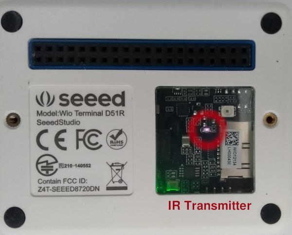
The IR Transmitter can be used to control various Multimedia devices around your home that have a IR receiver. To use the IR Transmitter the adafruit_irremote library needs to be copied to CIRCUITPY/lib.
The IR transmitter is used with board.IR and setup with the pulsio library.
pulseout = pulseio.PulseOut(board.IR, frequency=38000, duty_cycle=2 ** 15)
This example is a modification of the adafruits IR transmitter example code.
#Wio Terminal
#based on
#https://learn.adafruit.com/infrared-ir-receive-transmit-circuit-playground-express-circuit-python/ir-test-with-remote
import time
import adafruit_irremote
import pulseio
import board
from digitalio import DigitalInOut, Direction, Pull

# Create a 'pulseio' output, to send infrared signals on the IR transmitter @ 38KHz
pulseout = pulseio.PulseOut(board.IR, frequency=38000, duty_cycle=2 ** 15)
# Create an encoder that will take numbers and turn them into NEC IR pulses
encoder = adafruit_irremote.GenericTransmit(header=[9500, 4500], one=[550, 550],
                                            zero=[550, 1700], trail=0)

but1 = DigitalInOut(board.BUTTON_1)
but1.direction = Direction.INPUT
but1.pull = Pull.DOWN
but2 = DigitalInOut(board.BUTTON_2)
but2.direction = Direction.INPUT
but2.pull = Pull.DOWN

led = DigitalInOut(board.LED)
led.direction = Direction.OUTPUT

while True:
    if not but1.value:
        print("Button 1 pressed! \n")
        led.value = True
        encoder.transmit(pulseout, [255, 2, 255, 0])
        led.value = False
        # wait so the receiver can get the full message
        time.sleep(0.2)
    if not but2.value:
        print("Button 2 pressed! \n")
        led.value = True
        encoder.transmit(pulseout, [255, 2, 191, 64])
        led.value = False
        time.sleep(0.2)
This example transmits one of two IR signals depending if Button 1 or Button 2 is pressed. A full explanation is available at the adafruit link at the top of the example.
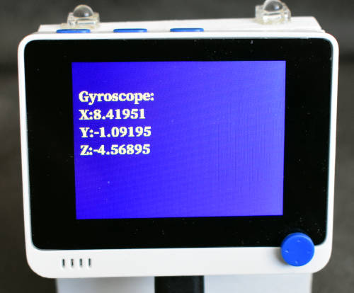
Accelerometer
The Wio Terminal Accelerometer is used to detect the orientation and motion of the device. It can also detect if it is being tapped or shaken giving further input option along with the buttons and 5 way switch.
The Accelerometer is the LIS3DHTR which is directly compatible with the adafruit_lis3dh library. Copy this library to the CIRCUITPY/lib folder.
The LIS3DHTR is accessed through a I2C port so needs to be setup the same as an external device using the dedicated Gyroscope I2C pins.
board.GYROSCOPE_SCL, board.GYROSCOPE_SDA
To initialise the Accelerometer use these commands
i2c = busio.I2C(board.GYROSCOPE_SCL, board.GYROSCOPE_SDA)
int1 = digitalio.DigitalInOut(board.GYROSCOPE_INT)
lis3dh = adafruit_lis3dh.LIS3DH_I2C(i2c, int1=int1)
This example shows the XYZ orientation of the Wio Terminal. If the case is tapped or shaken then it will show that it has detected them.
import time
import board
import busio
import digitalio
import adafruit_lis3dh

i2c = busio.I2C(board.GYROSCOPE_SCL, board.GYROSCOPE_SDA)
int1 = digitalio.DigitalInOut(board.GYROSCOPE_INT)
lis3dh = adafruit_lis3dh.LIS3DH_I2C(i2c, int1=int1)

lis3dh.set_tap(2, 100)
while True:
    if lis3dh.tapped:
        print("Tapped!")
        time.sleep(0.01)
    if lis3dh.shake(shake_threshold=10):
        print("Shaken!")
    x, y, z = lis3dh.acceleration
    print(x, y, z)
The Tap option lis3dh.set_tap(2, 100) can be used a a single or double tap. Currently set to 2 as a double tap. 100 is the sensitivity, increase to make less sensitive and use a lower number to make it more sensitive.
The shake threshold is used to adjust the sensitivity of detecting a shake type movement.
Buzzer
The Buzzer plays tones at different frequencies and duration's which can simply be controlled to make audio feedback for your programms.
The simpleio library is required so should be copied over to the CIRCUITPY/lib folder. The buzzer is on pin board.BUZZER
This is a simple example to play a few tones.
import board
import simpleio
buzz = board.BUZZER

simpleio.tone(buzz, 1000, duration=0.4) #pin, frequency, duration
simpleio.tone(buzz, 800, duration=0.4)
simpleio.tone(buzz, 600, duration=0.4)
simpleio.tone(buzz, 400, duration=0.2)
simpleio.tone(buzz, 200, duration=0.2)
Microphone
The built in PDM microphone can be used to sample sound for interactions with your programs or be used as a sound level sensor. This guide uses adafruits example for a sound level sensor.
Using the built in audioio library the microphone needs to be initialised with the PDM audio pins. Though I was expecting to use the 'board.MIC' pin, this guide needs board.I2S_BCLK for the clock and board.I2S_SDIN for the data.
Initalise the microphone with
mic = audiobusio.PDMIn(
    board.I2S_BCLK,
    board.I2S_SDIN,
    sample_rate=16000,
    bit_depth=16
)
This example show the sound level as a floating point number
#https://learn.adafruit.com/adafruit-pdm-microphone-breakout/circuitpython
#https://learn.adafruit.com/sensor-plotting-with-mu-and-circuitpython/sound
import array
import math
import time

import audiobusio
import board


def mean(values):
    return sum(values) / len(values)


def normalized_rms(values):
    minbuf = int(mean(values))
    sum_of_samples = sum(
        float(sample - minbuf) * (sample - minbuf)
        for sample in values
    )

    return math.sqrt(sum_of_samples / len(values))


mic = audiobusio.PDMIn(
    board.I2S_BCLK,
    board.I2S_SDIN,
    sample_rate=16000,
    bit_depth=16
)
samples = array.array('H', [0] * 160)
mic.record(samples, len(samples))

while True:
    mic.record(samples, len(samples))
    magnitude = normalized_rms(samples)
    print(((magnitude),))
    time.sleep(0.1)
Font File for Examples
The Open Sans font is available free from google. This has then been converted to a pcf file using FontForge. A full guide is on the adafruit website https://learn.adafruit.com/custom-fonts-for-pyportal-circuitpython-display
Open Sans Serif 22 pcf file download
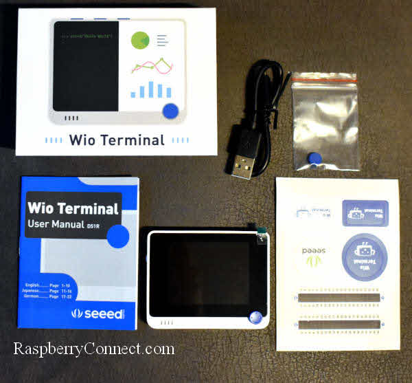
Thank you to Seeed Studio for supplying the Wio Terminal used in this guide.





I have not used the SD card reader on the Wio Terminal but you should be able to use any Adafruit SD card reader examples with a few modifications.
At the top of this article, there is a list of all the devices available with the 'board' command. Within this is 'SD_CS', 'SD_DET', 'SD_MISO', 'SD_MOSI', 'SD_SCK'. These are the connections for the SD card.
The Adafruit SD card example at https://learn.adafruit.com/adafruit-micro-sd-breakout-board-card-tutorial/circuitpython uses the following code to setup the SD card.
spi = busio.SPI(board.SCK, MOSI=board.MOSI, MISO=board.MISO)
# Use board.SD_CS for Feather M0 Adalogger
cs = digitalio.DigitalInOut(board.SD_CS)
# Or use a digitalio pin like 5 for breakout wiring:
#cs = digitalio.DigitalInOut(board.D5)
If you modify the connections it "should" work on the WIO Terminal
spi = busio.SPI(board.SD_SCK, MOSI=board.SD_MOSI, MISO=board.SD_MISO)
cs = digitalio.DigitalInOut(board.SD_CS)
Then with the libraries
import adafruit_sdcard
import storage
The rest of the Adafruit example article to setup the SD card reader will work with the commands:
sdcard = adafruit_sdcard.SDCard(spi, cs)
vfs = storage.VfsFat(sdcard)
The adafruit_sdcard library example is at https://docs.circuitpython.org/projects/sd/en/latest/ for further info.
You should just need to change the SDK, MOSI, MISO & CS references to 'SD_CS', 'SD_DET', 'SD_MISO', 'SD_MOSI', 'SD_SCK'
As I say this is untested but follows how the other devices on the WIO Terminal work with Circuit Python.
If we could get an example of how to define the UART pins to talk to the GPS.. that would be fantastic!
Ken
Thank you, I have not used the Wio LoRa GPS module but I do have a basic GPS module which uses UART a connect. I have only used it with CPython which worked with standard GPS libraries.
Have you tried the adafruit GPS library in CircuitPython 7.
https://learn.adafruit.com/adafruit-ultimate-gps/circuitpython-parsing
https://github.com/adafruit/Adafruit_CircuitPython_GPS